


News
The Cost-Effective Benefits of OTA Testing for Automakers
By running OTA tests regularly, automakers can identify and fix issues before they become major problems. This helps to reduce the cost of production, speed up time to market and
2023-11-08
White paper
This white paper explores the benefits of using RanLOS Compact Antenna Test Range (CATR) solution for full-vehicle antenna testing. RanLOS’s cost-effective CATR solution helps test engineers and automakers to measure connectivity and antenna performance more efficiently during the product development process.

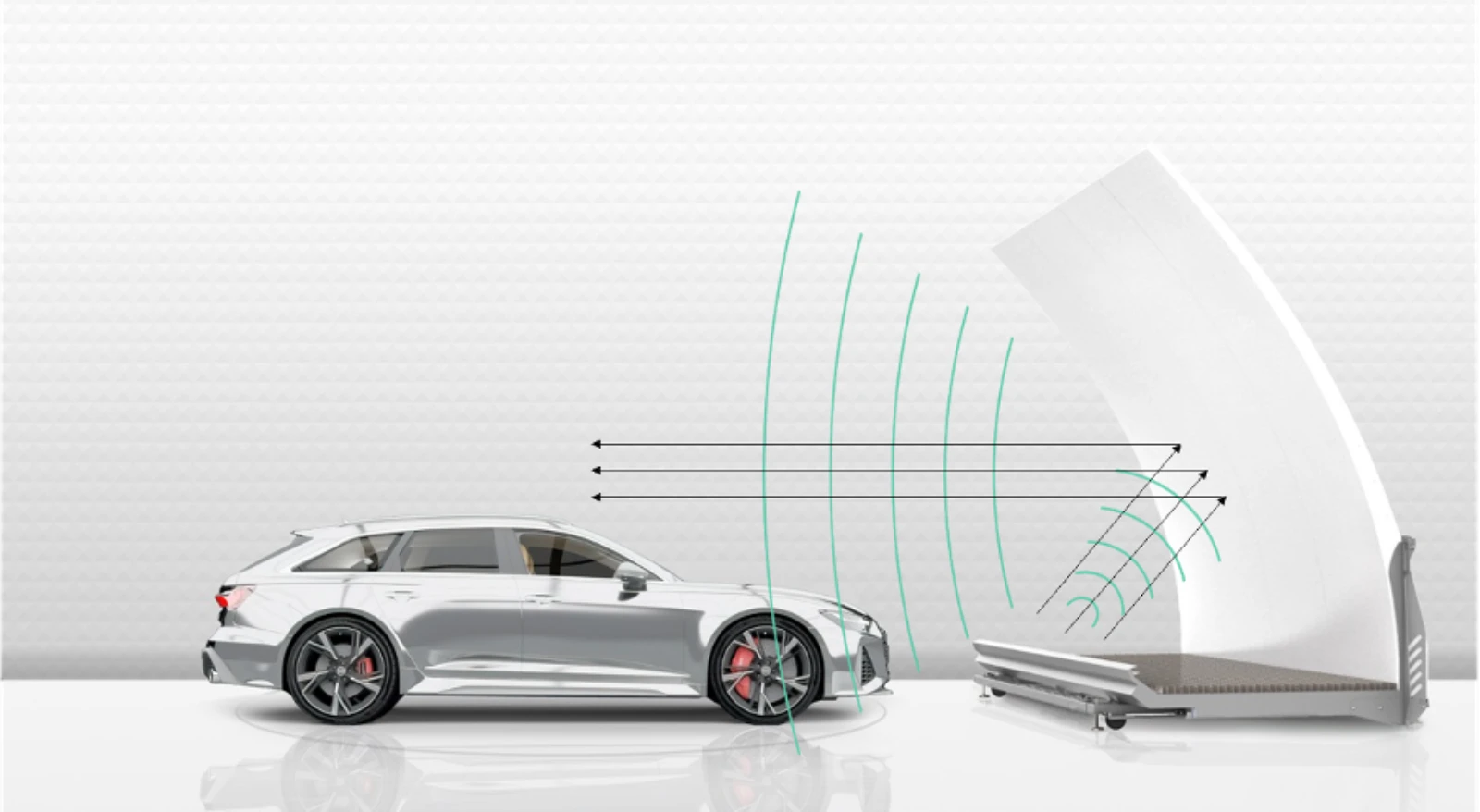
Compact Antenna Test Range (CATR) can be used to measure large devices such as cars, at a significantly shorter distance than in traditional far-field test ranges. A source antenna (feed) is used to radiate a spherical wave in the direction of a reflector, that transforms the wave into a plane wave. The device under test (DUT) is illuminated by the plane wave and a far-field measurement can hence be performed.
When performing frequent testing, accuracy and efficiency are equally important. Traditional far-field test ranges, while effective, often require substantial distances to accurately measure large devices such as vehicles. However, the CATR solution has made it easier, enabling engineers and researchers to conduct measurements at significantly shorter distances without compromising accuracy.
The RanLOS test system consists of a cylindrical reflector fed by a linear array of dual-polarized antennas. The reflector is 4.2 meters wide and 3.15 meters tall and can be used to measure a wide range of frequencies. Compared to many other CATR methods, RanLOS has a more flexible solution. The RanLOS test system is easy to install and can be added to already existing EMC chambers. For RanLOS test system the feed is mounted together with the reflector. This means no complicated and time-consuming feed alignment during the installation is needed. Together with the fact that the system is portable on wheels, it is easy to upgrade existing EMC chambers by just rolling in the system. The cylindrically shaped reflector is also scalable in width and can be made in sections and is less expensive to manufacture compared to double-curved reflectors.
The RanLOS system generates a single plane wave. This plane wave is incident on the equipment under test (EUT) from an incident angle determined by the rotation of the EUT. The polarization of the incident wave can be either linear or elliptical (e.g., circular), depending on how the two ports on the RanLOS system are fed. RanLOS software controls the whole process, from calibration, and controlling the turntable or positioner, to measurement and data plotting and analysis. The user gets full control over the whole test process and can easily perform a measurement in 5 easy steps. The system enables far-field measurements of full vehicles, antennas, communication systems, base stations, and other connected devices at only a few meters distance. The RanLOS software is compatible with all standard Vector Network Analyzers and Communication Testers. The software also supports positioner controllers from major manufacturers and adding new functions and/or instrument drivers is easy.
Viable for Existing Anechoic EMC Chambers
In a typical far-field anechoic chamber, the electromagnetic field radiated from the transmitting antenna propagates as a spherical wave and reaches the test area, the quiet zone. At this time, even in an anechoic chamber, in addition to direct waves from the transmitting antenna, reflected waves from the floor, ceiling, and side walls simultaneously enter the test zone. This results in a distribution of amplitude and phase fluctuations within the test zone, depending on the strength and phase of the reflected waves.
Due to these reasons, a better solution is to use a CATR system. The CATR system generates plane waves where the radiated power, in directions other than the front direction, is smaller than the radiation from the transmitting antenna in a normal far-field anechoic chamber. In other words, the propagation is less affected by the floor, ceiling, and side walls.
In normal spherical wave propagation in a far-field anechoic chamber, there is a free space loss in which the received power decreases with distance because the surface area of the spherical wave increases with distance and the power density decreases.
In the CATR environment, since it is a plane wave, the power density does not change with respect to the distance in the depth direction within the test zone. That is, the received power at the front and back edges of the test zone is the same. Meaning that the RanLOS CATR solution is a perfect solution for existing anechoic EMC chambers.
Precision in a compact form
With a reflector height of 3.15 meters, the RanLOS CATR system can be efficiently deployed in smaller chambers or testing environments, saving valuable space and facility investments without compromising measurement accuracy. RanLOS reflector is a very cost-efficient solution to enable far-field measurements. Crafted from precision-engineered carbon fiber, the reflector boasts exceptional durability and precision, ensuring long-lasting performance and minimal maintenance requirements.

Modularity for Frequency Versatility
RanLOS has a modular design using different antenna arrays (feed arrays) to measure desired frequency while using the same reflector. The feed array is easily exchangeable, and it covers an octave bandwidth. To cover the 0.7 to 6 GHz frequency band, the most used frequencies for vehicular communication systems today, three feed arrays are needed. Feed arrays for higher frequencies are on the roadmap, so existing customers can easily upgrade with no need to alter the reflector. This adaptability ensures that RanLOS can effectively accommodate a wide spectrum of frequencies, making it a versatile choice for researchers and engineers working on diverse projects.
Invaluable data for decision-making
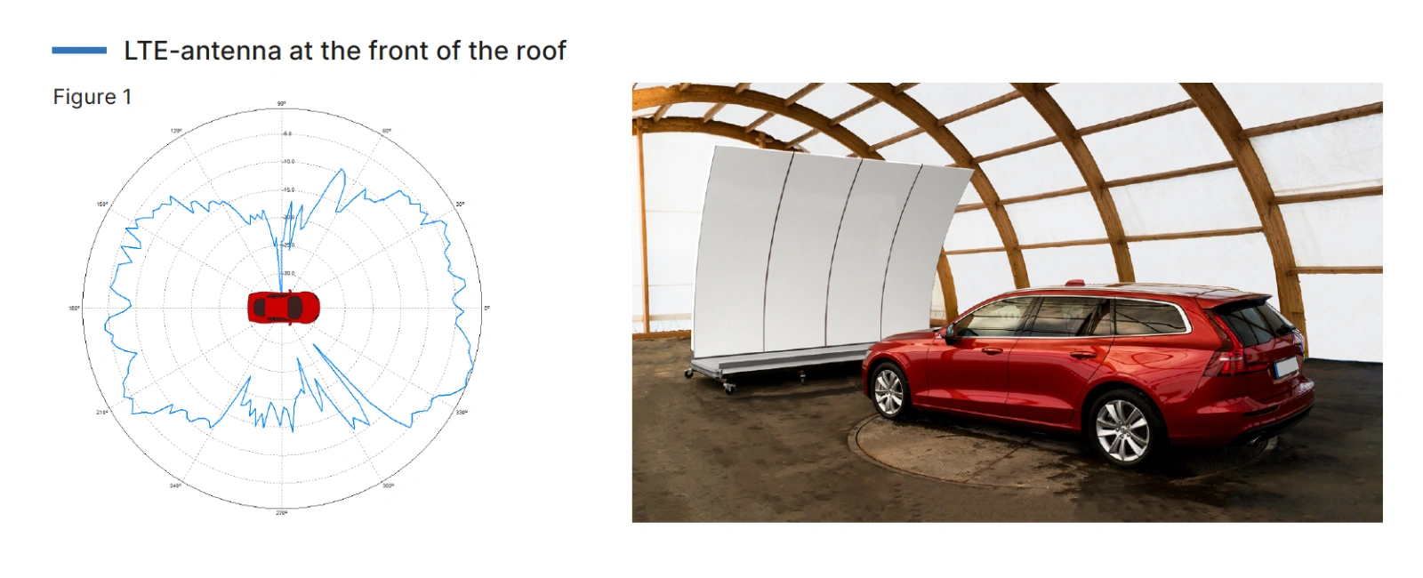
The RanLOS system is used to do Over-the-Air (OTA) measurements and can measure, for example, how antennas radiate in different directions (antenna radiation pattern) or the quality of a communication system. This is important information for the engineer in order to understand how, for example, vehicles receive and transmit data (connectivity/throughput).
Antenna radiation patterns can be presented in a polar graph (see Figure 1). The graph makes it possible to detect weak directions where the antenna has inferior performance. In the graph in Figure 1 the red trace represents the radiation pattern with the antenna placed at the back of the roof, and the blue when the antenna is moved to the front of the roof. As can be seen in the graph, it is not only the antenna design that is of importance but also the position of the antenna. Therefore, it is important for the design engineer to have a tool to understand the impact of both the antenna design and its position on the vehicle.
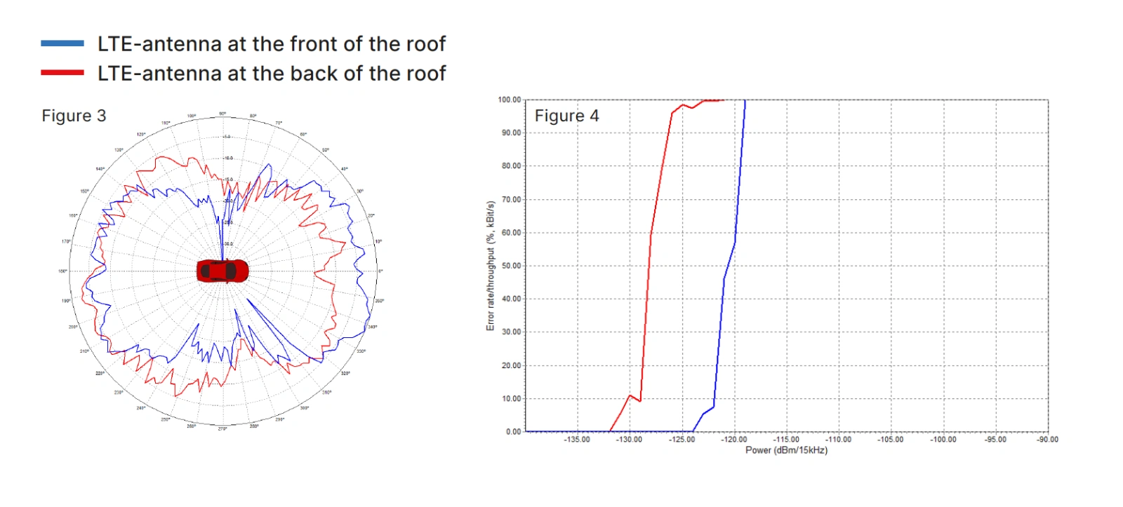
The quality of the wireless connection can be measured with a Radio Communication Tester, simulating wireless communication with a vehicle under test. The test result is presented in a throughput graph (see Figure 2). The graph presents the data throughput as a function of power for one angle. In this graph, it’s possible to identify the receiver threshold which could, e.g., be defined as the received power level when the throughput is 50% of maximum. This is an important quality parameter of the communication system. As can be seen in Figure 2 the step from 100% to 0% throughput is very steep, and therefore the threshold is rather easy to find and a practical parameter to be used in the engineering work. It is also possible to measure and present the throughput for a full 360-degree revolution.
In Figure 3 it can be seen that the position of the antenna at the back of the roof is better for all directions except towards the forward direction, where the front positioned antenna has better coverage. For example, when the signal is transmitted/received towards the side, at a 100-degree angle, the difference is approximately 15 dB. If the throughput of the communication system is measured and presented at this angle the result is as in the throughput graph in Figure 4. The threshold clearly shows a worse communication quality, at this angle, when the antenna is placed at the front of the roof.
By using the threshold value together with Friis transmission formula it is possible to compute the maximum communication distance and thus the overall wireless performance of the vehicle. This important information can be obtained by adding, and using, the RanLOS test system in existing EMC chambers. In this way, it is possible to optimize the antenna’s position and compare different antennas and communication systems to improve the overall communication quality. See RanLOS Application Note: “Maximizing communication quality: Unlocking the optimal antenna placement for cars” for more details.

Based on many years of research with a focus on best performance vs price
RanLOS has its origins in several years of research and development at Chalmers University of Technology and was established by Professor Per-Simon Kildal in 2016. Professor Kildal was one of the foremost antenna experts in the world.
RanLOS holds patents globally and is recognized as an innovative supplier of CATR test systems for large test objects. RanLOS has been part of many different research projects where the products have been validated together with both customers and academia.
Below is a comparison between measurements done using the RanLOS test system and an accredited test facility using an NF-FF system. The device under test was an antenna mounted on the roof of a vehicle body. The measurement results show how RanLOS technology is reliable with results in line with advanced test facilities. These measurements, as well as many additional validation measurements, were performed during the Swedish government-funded project “Simulation and Verification of Wireless Technologies” (SIVERT).

There is an ongoing change where wireless systems are becoming more advanced and will require increasingly more tests in order to be verified. This places new demands on the measuring equipment in the lab and a need for efficient and affordable test solutions.
Only a handful of car manufacturers around the world have invested in their own test systems to measure connectivity on an ongoing basis. It is expensive, time-consuming, and difficult to calculate the return on investment with existing solutions. The consequence is that tests are done late in the development process, for example when the car can be driven on public roads or a test track.
RanLOS equipment is not intended as a certification system but as a tool to be used continuously during the product development process. The system is a complement during the development process and is used to optimize performance and prepare for certification.
In conclusion, CATR has made testing more versatile by enabling measurements at shorter distances. RanLOS aim is to make testing simple, accessible, and cost-effective. With RanLOS’ affordable solution, testing can be done every day if needed. In this way, customers can detect problems early and save both time and money by shortening their time to market and launching cars that meet the buyers’ high demands.
RanLOS solution has many advantages:
RanLOS CATR system is a perfect solution for existing EMC chambers since the characteristics of the plane wave results in that the propagation is less affected by floor, ceiling, and side walls and the power density does not change in the depth.
By using existing facilities, costs can be reduced without the need to construct a new anechoic chamber for antenna testing.
RanLOS uses a patented cylindrically shaped reflector that is less expensive to manufacture compared to double-curved reflectors and it is scalable in width and can be made in sections.
Test frequencies can be changed by easily replacing the feed array. (Realignment work is not required as only the antenna array at the reflector focus is replaced.)
By combining the turntable with a chassis dynamometer installed in the vehicle EMC anechoic chamber, it is possible to test the vehicle in driving mode and regeneration mode.
It is possible to combine ADAS functional testing and V2X communication quality evaluation.
Make sure to follow RanLOS at LinkedIn, have a look our latest news here or reach out to our employees.
By running OTA tests regularly, automakers can identify and fix issues before they become major problems. This helps to reduce the cost of production, speed up time to market and
Explore RanLOS cover feature in Microwave Journal: “A cost-effective method to measure vehicle antenna radiation patterns and data throughput”

RanLOS has achieved a significant milestone by securing an order from a European car manufacturer in the premium segment. The sale means that RanLOS will supply both hardware and software
| Cookie | Duration | Description |
|---|---|---|
| cookielawinfo-checbox-analytics | 11 months | This cookie is set by GDPR Cookie Consent plugin. The cookie is used to store the user consent for the cookies in the category "Analytics". |
| cookielawinfo-checbox-functional | 11 months | The cookie is set by GDPR cookie consent to record the user consent for the cookies in the category "Functional". |
| cookielawinfo-checbox-others | 11 months | This cookie is set by GDPR Cookie Consent plugin. The cookie is used to store the user consent for the cookies in the category "Other. |
| cookielawinfo-checkbox-necessary | 11 months | This cookie is set by GDPR Cookie Consent plugin. The cookies is used to store the user consent for the cookies in the category "Necessary". |
| cookielawinfo-checkbox-performance | 11 months | This cookie is set by GDPR Cookie Consent plugin. The cookie is used to store the user consent for the cookies in the category "Performance". |
| viewed_cookie_policy | 11 months | The cookie is set by the GDPR Cookie Consent plugin and is used to store whether or not user has consented to the use of cookies. It does not store any personal data. |

We aim to create a better connected society. To do so we need easy-to-use and flexible solutions for testing wireless performance over-the-air (OTA). It includes all relevant standards today and tomorrow; such as 3G, 4G, 5G, and WiFi. Work with us and start measuring easier, faster and smarter.