RanLOS Logo White 6pt
Categories
Application Notes Educational

RanLOS test technology – A unique solution for cost-effective OTA measurements

Home > News

2024-06
Application Note

RanLOS test technology -
A unique solution for cost-effective OTA measurements

Reliable and cost-efficient testing is important when developing wireless communication systems, especially in vehicles today. In this application note, we dive into this topic and introduce the RanLOS test technology, a unique solution designed specifically for Over-the-Air (OTA) measurements. 

RanLOS test technology - A unique solution for cost-effective OTA measurements

Illustration of RanLOS BeamForce 42 test system 

Introduction

RanLOS offers a reliable and cost-effective alternative to more expensive and advanced test solutions, enabling efficient testing and evaluation of antenna radiation patterns and communication system throughput. Its modular and upgradable design allows for easy adaptability and installation in diverse testing environments. 

This application note also dives into RanLOS straightforward measurement process, outlining how to perform a measurement in a few easy steps. Additionally, it highlights RanLOS’ compatibility with various industry instruments and communication standards, ensuring its versatility. 

By using the RanLOS test system, users and car manufacturers get a powerful test solution that can guarantee high quality and performance of their wireless communication systems, ultimately leading to more reliable and safer connected vehicles.

The need for test systems: Methods and solutions

The importance of a robust test philosophy in the development of wireless communication systems, particularly those used in vehicles, is essential. The complexity of these systems, which involve digital and analog subsystems along with extensive software, requires thorough testing to ensure customer satisfaction and the overall quality of the communication system in cars.

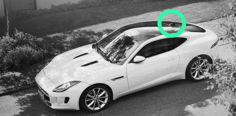
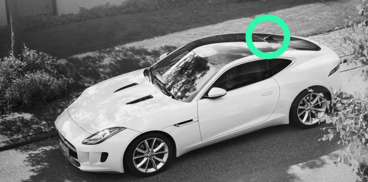
To measure the communication system of a vehicle you need to simulate the environment in which the vehicle will be used. The communication to and from a vehicle is typically between a car and the surroundings, i.e. other cars, base stations, road-side systems, etc. what we call vehicle-to-everything communication or V2X-communication. Since the antennas used for the communication are far apart and the communication is wireless, the communication is said to be in Over-the-Air (OTA) far-field conditions.

For final system verification or measurements during the development phase, we want to create far-field conditions. This is because obtaining accurate measurement results requires the antenna’s far-field conditions to be met. Therefore, the antenna under test (AUT) must be in the far field of the probe antenna, i.e. the antenna used for the measurement. This can be done in different ways. Perhaps the most obvious way is to use a large enough shielded room so that the AUT and the probe antenna is guaranteed to be at far-field distance for all frequencies of interest. The main disadvantage with this method is that the chamber must be very large, and therefore will be very expensive. 

A commonly used alternative method is to measure in the near-field at a short distance from the AUT. For this, we need to sample the field in many points on a sphere surrounding the AUT and then use complicated mathematical transformations to get the far-field performance of the AUT. The main advantage with this so-called NF-FF (near-field to far-field) method is that the chamber can be made smaller. However, the disadvantages are that we need a mechanically precise positioning device for the probe antenna, and we need to sample in many points on the surrounding sphere, higher frequencies require more points. This in combination with the necessary mathematical transformations will result in long measurement times. Also, the method is not suitable for direct throughput measurements. 

Besides the mentioned methods for creating far-field conditions for the AUT, there are other methods that do not require large distances and thus can be fitted into smaller chambers. 

One such method is to use a two-dimensional array of antennas that are individually amplitude and phase controlled. With such a configuration it is possible to create a plane wave (far-field) at a short distance in front of the 2D array. However, since controllable attenuators and phase shifters are required for all antenna elements in the array it is a complex construction, and a complicated calibration procedure is required. Another limiting factor is the rather limited frequency bandwidth. 

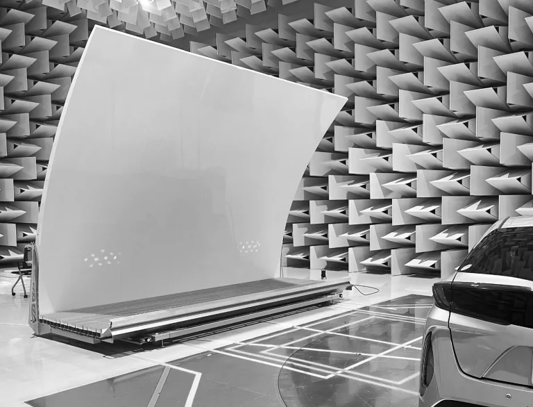
Instead of using a 2D array of antennas, a single antenna illuminating a shaped reflector can be used. This is a much more flexible solution which often is used in high-precision antenna test ranges, so-called compact antenna test ranges (CATR). In such a setup, the feed antenna is normally placed at floor level in a fully anechoic chamber and the double curved reflector is elevated to avoid the feed antenna blocking the field. The test zone where we will have the desired plane wave will therefore be at a certain height over the floor in the chamber, and thus the AUT must be placed on a tower. 

RanLOS test system is basically built on the same principle but instead of using a complicated double curved reflector, we use a single curved cylindrical reflector. The advantage is twofold. First, the reflector is cheaper to manufacture due to its simpler shape, and second, both the reflector and feed array can be placed on floor level in the chamber. The latter is an important advantage since the whole test system can be placed in a semi-anechoic chamber, e.g., an EMC chamber. Another important aspect is that the feed array and the reflector can be made as one unit, which makes it possible to make it mobile so that the test system easily can be rolled in and out of the chamber. Thus, allowing for the chamber to be used for dual purposes, e.g., EMC and antenna testing. The feed array in the RanLOS test system is a dual polarized passive antenna and as such can be used either as a transmitting or receiving antenna, allowing both antenna performance and throughput measurements.    

So, although the RanLOS test technology is less complex, it can deliver the same high measurement quality as expensive and advanced test facilities. 

Additionally, with RanLOS accessibility users can easily perform daily measurements throughout the development process, saving costs and speeding up time to market.

In summary, types of measurement solutions

  1. Far-field chamber, large and expensive
  2. Near-field to far-field method, smaller chamber than the far-field chamber, complicated and advanced equipment, need post-processing, expensive and limited frequency bandwidth
  3. Two-dimensional array of antennas, complicated design and calibration, expensive
  4. Single antenna with double curved reflector,
    smaller chamber, rather complicated, expensive
  5. RanLOS solution, smaller chamber, easy-to-use system that is easy to calibrate and very cost-effective compared to the other solutions

Short video of the benefits of RanLOS BeamForce 42 test system

How to perform a measurement in a few easy steps with RanLOS test system

  1. Select measurement set-up 
    • Align RanLOS measurement system 
    • Choose type of measurement set-up: Passive – Antenna radiation pattern 
    • Active – Wireless system throughput and performance 
    • Select instrumentation, Vector Network Analyzer, or Communication Tester 
    • Select positioner, turntable, etc. 

  2. Perform calibration 
    • Place the calibration antenna at the centre of the turntable 
    • Follow the guidelines in the software 

  3. Perform measurements
    • Place the device under test (DUT) in front of RanLOS BeamForce 42
    • Initiate RanLOS measurement software, select frequencies, angles, etc. 
    • Perform the measurements with the help of the software 

  4. Analyze and visualize measurement results
    • Tables 
    • Plots 
    • Graphs 
    • 1D, 2D, or 3D 
    • Mathematical analyzes 
    • Export to other software, etc. 

Do you want to learn more about RanLOS test technology? Make sure to download our free pdf version of this Application Note below and learn about RanLOS unique solution for cost-effective OTA measurements. ✅

RanLOS-5G-OTA Testing

RanLOS BeamForce 42 test system in Japan

Want to learn more?

Make sure to follow RanLOS at LinkedIn, have a look our latest news here or reach out to our employees. 

Other news & articles

Categories
Application Notes Educational

Why testing is vital when developing wireless communication systems for vehicles

2024-04-12
Application Note

Why testing is vital when developing wireless communication systems for vehicles

There is a critical importance of continuous testing when developing wireless communication systems for vehicles. Why is this important and how can car manufacturers perform tests during development in a convenient and cost-effective way? Let’s explore this in our application note below. 

RanLOS test setup for testing wireless communication systems for vehicles

Introduction

This application note emphasizes the critical importance of comprehensive testing in developing wireless communication systems for vehicles. These systems, characterized by complexity involving digital components, analog components, and software, demand thorough testing for both customer satisfaction and system reliability.

The theory of signal modulation underscores the significance of accurate signal detection at the receiver’s end, particularly in systems with higher modulation schemes that store more information. Natural and in-car disturbances impact signal quality and need to be considered when the test system is chosen to be used for measurements and verification of the vehicle communication system.

In conclusion, this application note highlights why it is important to perform tests when developing wireless communication systems for vehicles. It also presents RanLOS test system as a cost-effective and reliable solution to ensure optimum measurement performance.

Short description of a typical communication system

When establishing a wireless connection, the capacity and therefore the throughput is important. The communication system consists of a number of components and subsystems. It is a complex system with digital and analog subsystems and much software. Customer experience is of high importance and the quality of the communication system is very important. Testing the entire communication system in a car is therefore of high priority. In addition, a growing percentage of the vehicle’s technical performance depends on how well the communication system works. All this shows that tests of the communication system are a vital part of the development process of new vehicles.

A wireless communication channel uses a space in the frequency spectrum. In order to use the frequency space as efficiently as possible the frequency spectrum is divided into areas that can be used for different purposes and functionalities. The frequency space is then used for transferring digital data at a certain speed (capacity/throughput). To be able to communicate with as high capacity/throughput as possible, different modulation technologies are being used. High order modulation scheme enables high data rates but will also require a high signal-to-noise ratio (SNR).

QAM constellation diagrams

Examples of Quadrature Amplitude Modulation (QAM) constellation diagrams, 16 QAM, 64 QAM, and 256 QAM

Examples of Quadrature Amplitude Modulation (QAM) constellation diagrams, 16 QAM, 64 QAM, and 256 QAM.

Measurements with RanLOS test equipment

RanLOS test technology is based on practical parameters and is designed to be easy to use, cost-effective, and deliver excellent measurement quality. The test systems are designed to be used in anechoic chambers, semi-anechoic chambers, EMC chambers, open measurement sites, etc. 

The RanLOS test technology makes it possible to perform measurements in far-field conditions whilst the competitors mainly measure in near-field conditions and thereafter convert the result to far-field conditions with mathematical methods. This means that the RanLOS system is easy to use and that it is possible to supplement an already existing EMC chambers to do the measurement of the communication system in the vehicle.

Do you want to learn more about why testing is vital when developing wireless communication systems for vehicles? Make sure to download our free pdf version of this Application Note below. ✅

Want to learn more?

Make sure to follow RanLOS at LinkedIn, have a look our latest news here or reach out to our employees. 

Other news & articles

Categories
Application Notes Educational

Maximizing communication quality: Unlocking the optimal antenna placement for cars

2024-02-12
Application Note

Maximizing communication quality: Unlocking the optimal antenna placement for cars

To optimize the connectivity of the car, the position of the antennas is of high importance. In this application note, we explore how car manufacturers can maximize communication quality and unlocking the optimal antenna placement for cars.

antenna placement on modern car

Introduction

To optimize the connectivity of the car, the position of the antennas is of high importance. The car is normally made of metal parts which are acting as a ground plane, therefore the body of the car, i.e., the shape is very much affecting the antenna performance and thereby the connectivity. A relatively common vehicle antenna type is the shark-fin antenna that normally is placed on the roof of the car. It is important that the position of the antenna is optimized to get the best possible performance, both regarding the radiation pattern of the antenna and the connectivity.

The material of the roof has, of course, also a big impact on the overall performance of the system. The roof can be made of, for example, carbon fiber or glass (2). The roof can also be missing as in convertible cars (3), and then an alternative placement of the antenna is needed. This will for sure have an impact on the communication system performance.

An antenna mounted on a glass roof can be an attractive design but is not optimal for the performance of the communication system. The same applies to a car without a roof because the antenna must be placed in an alternative location, for example at the back of the car. In this application note, we will give examples on how different placements of the antenna can result in a reduction of the communication distance.

To be able to position the antenna with best possible communication quality as a result, there is a need of accurate test methods. Tests of a whole car are rather complex processes and expensive test facilities are needed. The needed test equipment is advanced and there is only a few of these test facilities available which make the verification cumbersome.

This is not a practical way forward; the engineers need to perform measurements throughout the whole development process. A misplaced antenna will result in unnecessary bad communication system performance such as, for example, to short communication distance and low communication capacity. RanLOS test setup is designed to be an easy-to-use measurement tool for antenna and throughput measurements. The test equipment is designed to be used in existing chambers or in open areas with weather protection. A long series of verifications and tests have been carried out to verify the quality of RanLOS test technology and these have shown that the technology is very reliable

Different antenna placements

The position of the antenna will give different communication performance. See the pictures below on different car models and antenna placements:

(1) Roof-mounted antenna with a position at the rear of the roof

(2) Modern car with glass or carbon fibre roof

(3) Cabriolet car without roof

Measurements with RanLOS test equipment

RanLOS test equipment is designed to be fitted into simple test sites or existing EMC chambers.

When the car is positioned in front of the RanLOS test setup, two different types of measurements can be performed to characterize the antenna and the quality of the wireless connection to the car…

Curious to learn more about how to maximize communication quality and unlock the optimal antenna placement for cars?
Make sure to download our free pdf version of the Application Note below. ✅

Want to learn more?

Make sure to follow RanLOS at LinkedIn, have a look our latest news here or reach out to our employees. 

Other news & articles

We aim to create a better connected society. To do so we need easy-to-use and flexible solutions for testing wireless performance over-the-air (OTA). It includes all relevant standards today and tomorrow; such as 3G, 4G, 5G, and WiFi. Work with us and start measuring easier, faster and smarter. 

Application Note - free download

The Application Note can be downloaded as a pdf after submitting the details below. ✅

Application Note - free download

The Application Note can be downloaded as a pdf after submitting the details below. ✅

Application Note - free download

The Application Note can be downloaded as a pdf after submitting the details below. ✅

Free download ready. ✅

Great work! You can now download the full pdf for our application note “RanLOS test technology – A unique solution for cost-effective OTA measurements” below.

For more news and papers: ranlos.com/news

Free download ready. ✅

Great work! You can now download the full pdf for our application note “Why testing is vital when developing wireless communication systems for vehicles” below.

For more news and papers: ranlos.com/news

Free download ready. ✅

Great work! You can now download the full pdf for our application note “Maximizing communication quality: Unlocking the optimal antenna placement for cars” below.

For more news and papers: ranlos.com/news