Technology

Far-field measurement,
a few metres away.

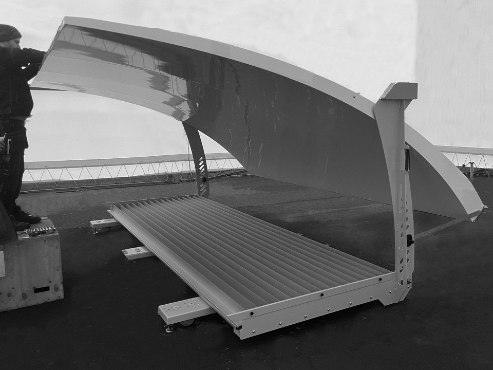
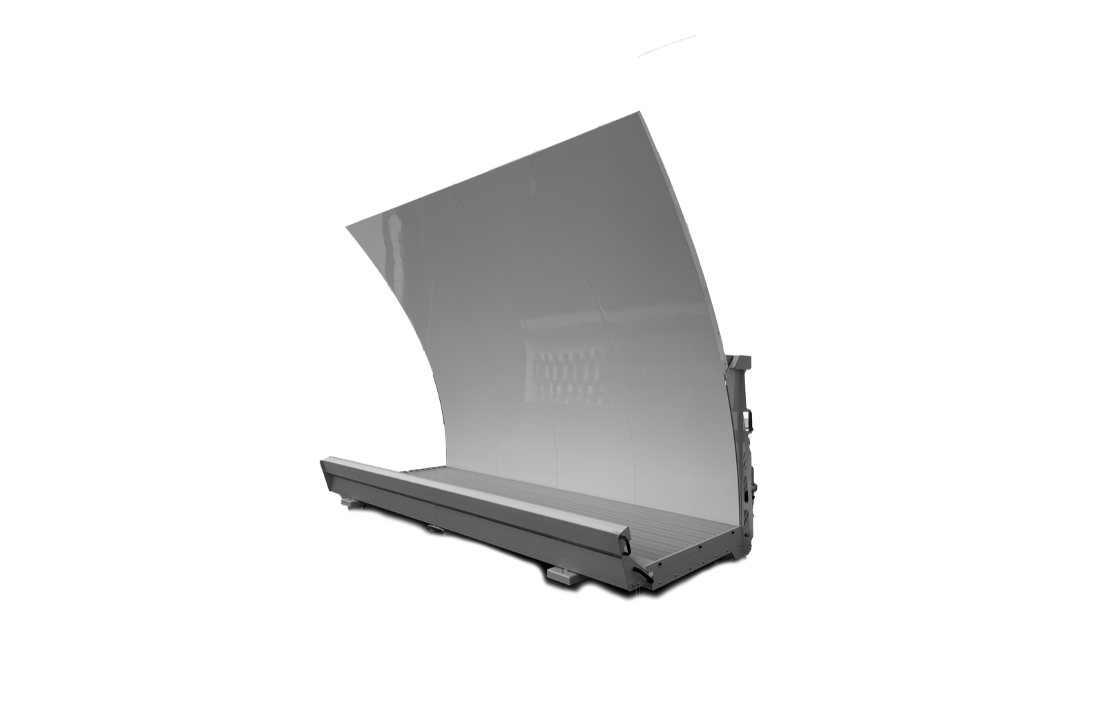
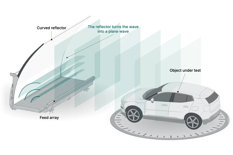
BeamForce is a compact antenna test range (CATR) in one unit. A linear feed array illuminates a cylindrical reflector, which turns the signal into a plane wave in the test zone, so the complete vehicle or UAV on the turntable is measured under far-field conditions. It rolls into the chamber, tent or lab you already have.

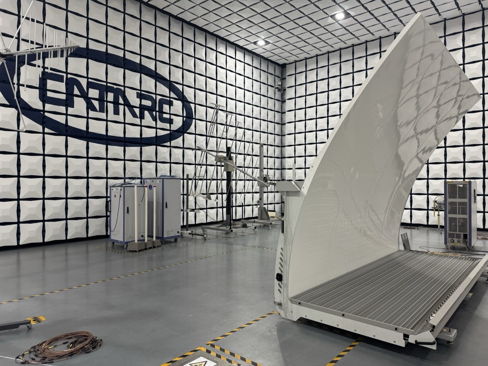
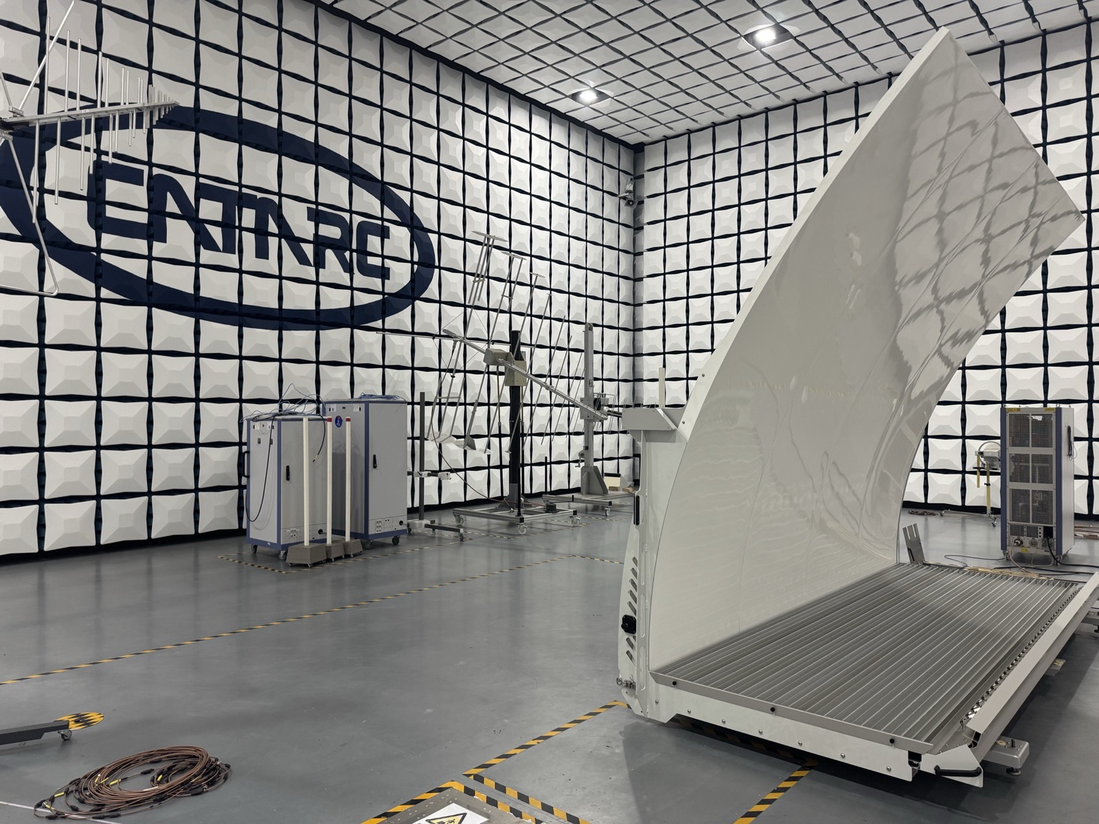
RanLOS test solution in the CATARC chamber, China, 2026
01 · Our roots

A compact antenna test range,
from research at Chalmers.

Random Line-of-Sight. RLOS, the method in our name. RLOS, Random Line-of-Sight, builds on research by Per-Simon Kildal’s group at Chalmers. The method recreates the road situation, line-of-sight (LOS) from a random angle, in a room you already have, with the same plane wave from every angle, in a repeatable way. It is published and validated against accredited near-field/far-field measurements.

BeamForce 42 from the side: the feed array at floor level sends the signal to the cylindrical reflector, which sends it on as a plane wave through the test zone to a vehicle on a turntable
Illustration, not to scale.
02 · How it works

Random Line-of-Sight.
One plane wave, every angle.

On the open road and in the air, one direct path dominates, and nothing makes up for a weak direction. BeamForce reproduces that in your own chamber. The reflector turns the feed array’s signal into a plane wave a few metres away, and the turntable brings the vehicle or UAV through it, one angle at a time.

Line-of-sight vs multipath, in depth
Illustration, not to scale and not a measurement.

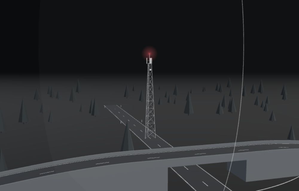
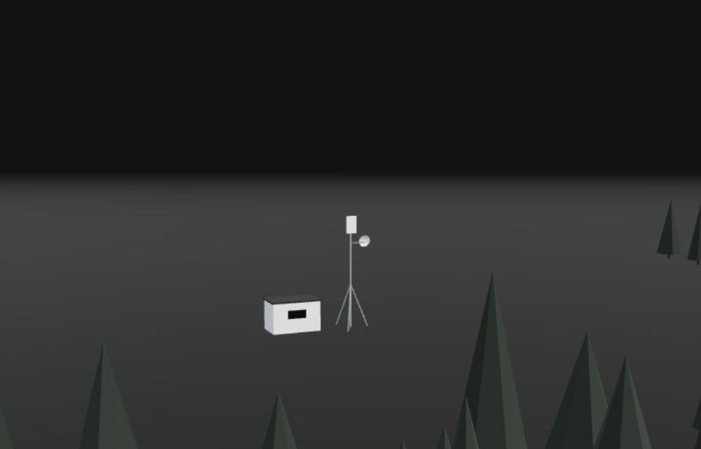
Far from the mast, the wave arrives flat.Far from the ground station, the wave arrives flat.

One direct path, from an angle that keeps changing.

The far field, a few metres away.

Every angle, one at a time.Every angle, during development.

Weak directions, found before the road.Weak directions, found before the field.

In real use
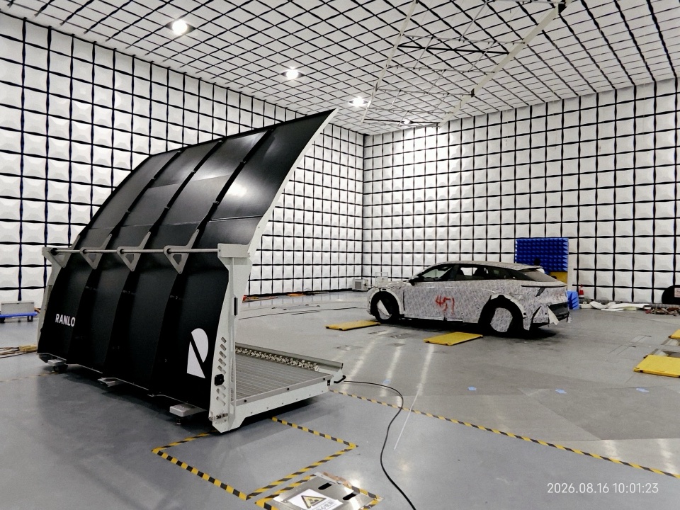
BeamForce 42 in a large EMC chamber, a camouflaged vehicle on the turntable behind it
BeamForce 42 with a vehicle at CATARC, China, 2026.
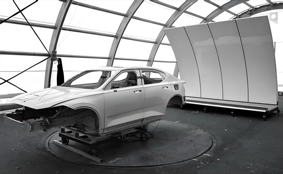
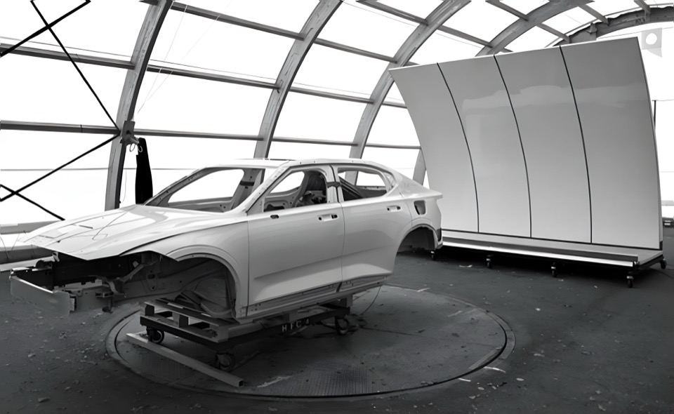
A car body on the turntable in the test tent, the curved reflector of BeamForce behind it
The test tent outside Gothenburg.
03 · Proof

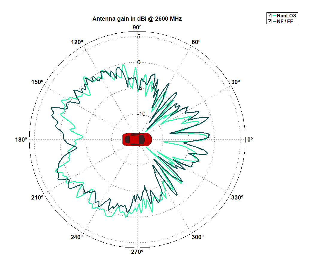
Comparable to advanced, more expensive test facilities.

Measured side by side with the CATARC chamber in China and with an accredited near-field/far-field range. Further developed in SIVERT 1 and 2, coordinated by Volvo Cars.

04 · BeamForce 42

In use within a day of delivery.

Drag to turn it. Every part has a job.

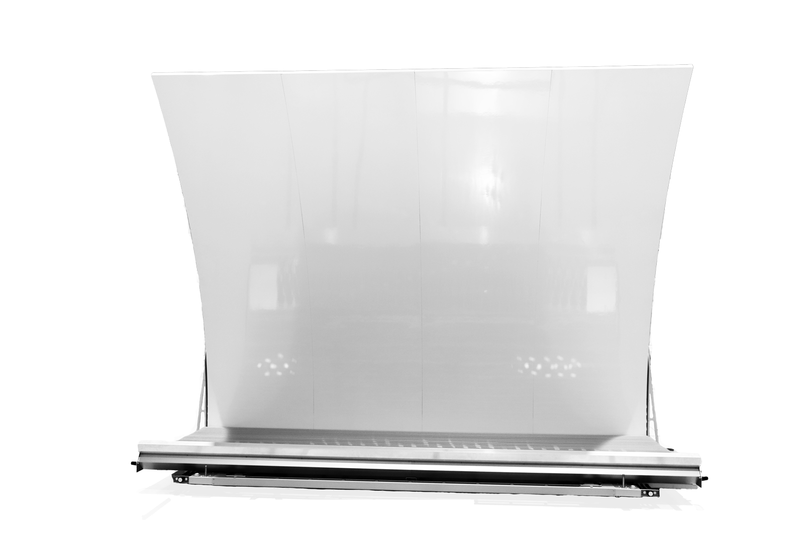
  1. The curved reflector turns the feed’s signal into a plane wave – far-field conditions at short distance.

    A cylindrical reflector, 4.2 m wide, fed by a dual-polarised linear antenna array.

  2. Exchangeable feed arrays (BeamArray) cover 0.7–6 GHz. Start with the bands you need and add the rest later.

    Upgradeable to higher frequencies. Dual-polarised, both polarisations at once with a 4-port instrument.

  3. Rolls on its own wheels into an existing chamber, tent or lab.

    In use within a day of delivery.

  4. 1.9 × 3.4 × 4.4 m (D × H × W). Quiet-zone STD below 1.6 dB.

    Repeatability < 0.15 dB. Semi-3D with BeamTilt.

  1. Complete cars, trucks and bodies-in-white. Complete UAVs, vehicles and platforms. 0.7–6 GHz – 4G, 5G, V2X and WiFi.

    Passive: antenna radiation patterns with a vector network analyser. Active: throughput with a communication tester, up to 2×2 MIMO.

Shown: BeamForce 42. More products can be found via the link below.

All products
BeamForce 42, side
Drag to turn
05 · Measurement modes

Two ways to measure with a RanLOS setup.

Source: RanLOS product brochure PB100-4, measurement setups.

06 · Deep dive

Vocabulary – line-of-sight, multipath and more.

LOS vs RIMP: two reference environments

One direct path, from an angle that keeps changing. On an open road, or in the air, one direct path dominates: the line of sight (LOS). The angle between that path and the vehicle changes all the time, at every bend and junction. Random Line-of-Sight (RLOS) describes performance across all those angles. “Random” refers to the geometry, not to the measurement.Over open terrain, water and treetops, one direct path dominates: the line of sight (LOS). As the drone flies, banks and turns, the angle between that path and the drone changes all the time. There is no alternative signal path: a weak direction becomes a weak link. Random Line-of-Sight (RLOS) describes performance across all those angles.

  • Many reflections RIMP

    In a city, or a reverberation chamber, signals arrive from all directions. Reflections make up for a weak direction.

  • Line of sight LOS

    On the open road or in the air, one direct path. Nothing makes up for a weak direction, and the link may fail.

Random Line-of-Sight goes back to Professor Per-Simon Kildal’s research at Chalmers University of Technology. Sources: white papers WP101 (pp. 2–6) and WP102 (pp. 2–3); ranlos.com/about-us.

Glossary · 14 terms
Antenna pattern (radiation pattern)
Shows how an antenna transmits and receives in different directions, often drawn around the vehicle, 0–360 degrees.
CATR
Compact Antenna Test Range. An antenna illuminating a shaped reflector creates a plane wave at a short distance, so far-field conditions fit in a smaller chamber. RanLOS uses a cylindrical reflector fed by a linear feed array, with reflector and feed array at floor level, in one unit.
EMC chamber
A shielded room where vehicles and electronics are tested against electromagnetic interference. Many vehicle manufacturers already have one.
Far field
Far from the transmitter the wave fronts are practically straight: a plane wave. Vehicles and drones communicate under far-field conditions, and an accurate antenna measurement needs them too.
Feed array
A dual-polarised array sends the signal towards the reflector. Exchangeable arrays cover 0.7–6 GHz.
LOS, line-of-sight
A radio environment where the direct signal path dominates, with no significant reflections. Typical on open roads and highways, and for drones over open terrain or at high altitude.
MIMO
Using multiple antennas to improve data throughput and reliability. One BeamForce 42 measures up to 2×2 MIMO.
Near field, NF-FF
Measuring close to the object: the field is sampled in many points on a sphere around it and converted to far field with mathematical transformations. The chamber can be smaller, but it needs a precise positioner, many points and post-processing, and it is not suited to direct throughput measurements.
OTA
Over-the-air. Testing a complete, integrated wireless product in its real configuration, not the components in isolation.
Plane wave
A wave whose fronts are practically straight, as when the signal comes from a transmitter far away. In BeamForce a curved reflector turns the feed array’s spherical wave into a plane wave.
Quiet zone (test zone)
Where the plane wave is uniform. The object under test sits there, on a turntable.
Random Line-of-Sight (RLOS)
A statistical model for line-of-sight environments: the channel is stable, but the angle to the other end changes all the time. “Random” refers to the geometry, not to the measurement. It goes back to Professor Per-Simon Kildal’s research at Chalmers.
RIMP
Rich Isotropic Multipath. Signals arrive from many directions through reflections and scattering, as in cities, tunnels and parking structures, or in a reverberation chamber.
Throughput
Measured over the air in active mode: a communication tester acts as the base station and talks to the vehicle’s own modem. Throughput is highest at high signal levels and falls as the level approaches the radio module’s sensitivity.

Sources: application notes AN100-2 and AN102-2; white papers WP101, WP102 and WP103; product brochure PB100-4; Microwave Journal, September 2023.
Contact RanLOS

All fields are required unless marked optional.

What do you want to test?

Tell us a little about what you need.